

Radio Servicing Information
For use by legally qualified and licensed repairers only
Countries have laws regulating who is legally allowed to repair or work on electrical equipment that will be plugged into the mains electricity supply. This is to protect the public from the risk of electric shock. If you are not lawfully allowed to repair electrical equipment yourself, you must find an electrician, a licensed electrical mechanic or electrical contractor or electronic technician to do any work on the equipment.
Different countries use electricity supply at different voltages. The United States uses 110-120 volts AC. The United Kingdom and Australia (amongst many other countries) uses 240 volts AC. Any electric shock at Voltage 110v or above is likely to be lethal.
Many types of early consumer electronic equipment was constructed at a time when electrical safety was not as carefully considered as is required under manufacturing laws today, and many early radio sets etc have mains electricity wiring and metal mains voltage terminals fully exposed to be touched once the metal chassis is removed from the wooden case or bakelite housing.
This is why any electrical work to restore or repair an old radio must be done by a licensed qualified technician.
YOU MUST NOT ATTEMPT TO REPAIR THE RADIO YOURSELF UNLESS YOU ARE LEGALLY ALLOWED TO DO SO.
UNUSUAL POWER SUPPLIES
A typical radio requires two different voltages, a high tension and a heater supply. The power source available, and the valves that are fitted, will determine the power supply. There are many variations. The radio power supply must convert the locally available power, to a high tension for the valves, and a low tension for the filaments/heaters, and sometimes a bias supply as well. The early power supplies had naming scheme which depended on the batteries used. This is a convenient way to refer to them. The filament supply or Low Tension (LT) was called the A supply. The High Tension (HT) was called the B supply. The bias supply, if there was one, was called the C supply. If a different high tension was required, the higher one was called the B++ or B1, and the lower one was called the B+ or B2.
One way to approach power supplies, is to look at the subject historically and follow the developments of domestic mains power and how the radios adapted.
Many houses in the 1920s did not have ANY mains 240 volts AC power supplied at all, and used candles or gas for lighting. The radios ran from batteries. As power was connected to homes, the battery radios used a Battery Eliminator to supply the B voltage. Some houses had 100 volts DC, others had 220 volts AC, other countries had different voltages. The radios with an AC supply could use a transformer to convert the mains voltage to A and B voltages. Homes with a DC supply, required a different approach to generate the B supply, often using a vibrator and series filament connections. Imported radios from Europe or the USA sometimes had different voltage mains, or 110 volts AC, and sometimes did not have a mains transformer. Farms had a 32 volt DC system running from a diesel or petrol generator. Cars had a 6 or 12 volt DC battery.
BATTERY POWERED SETS
These sets have a battery to supply the A and B supplies, and they are usually individual batteries. Some sets had a combined battery, but these were not popular as the A and B batteries would run down at different rates. Commonly the A battery would go flat first. The definition of a torch applies to a battery radio, "a place to store flat batteries". Replace them. Ordinary D cells (1.5 V) are suitable for the A supply. Ordinary 9 volt batteries connected in series (90 volts) are suitable for the B supply. Use the existing polarised plugs. Disassemble the old battery, and use the connector. Make a battery holder the same size as the old battery, and cover it with the cardboard outer of the old battery. Common faults are leaking batteries, which corrode the plugs, wires, and battery holders. Sometimes they corrode the electronics, but manufactures would normally place the battery where leakage would not harm the components.
BATTERY ELIMINATORS
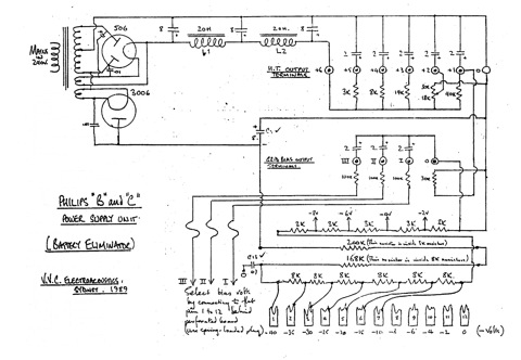
When homes became connected to electricity, they could still use their battery powered radio, by replacing the expensive B battery with a mains powered supply, called a B battery eliminator. This usually supplied the C bias as well. Flying leads from the radio were used with banana plugs, to connect the B voltage which was usually 100 volts (and sometimes a B2 voltage of 50 volts). There was also a C lead and plug for the negative bias (which was commonly minus 10 to 15 volts). The A battery eliminator was not successful as large electrolytic capacitors had not been developed. It was quite common to have a trickle charger connected to a large accumulator, for the A supply. The A supply accumulators were usually 2 volt lead acid batteries, and commonly provided 2, 4 or 6 volts for the filaments.
The Philips eliminator was made in Holland and was very popular in Australia, costing 9 pounds and 15 shillings in the 1920s. Quite a few still survive and are usually in good condition. The Philips 3003 model has a transformer and a full wave rectifier valve (type 506), with a capacitor and choke filter, to provide the B voltage. The C supply has an independent half wave rectifier valve (type 3006), capacitor and resistors. The various voltage tappings are provided by resistors. The Philips 3009 model has a transformer and a full wave rectifier valve (type 506), with a capacitor and choke filter, to provide the B voltage. The C supply negative bias is provided by resistors in the HT negative lead, in the traditional back bias method. The Philips 372 model has the valve visible on the top. The Philips eliminators usually have a good transformer, rectifier valve and choke, but the capacitors require a little time, before they reform. The resistors for the voltage tappings are commonly open circuit and are made of fine resistance wire wound on a glass rod. The wire can be rejoined.
VIBRATORS
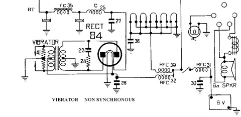
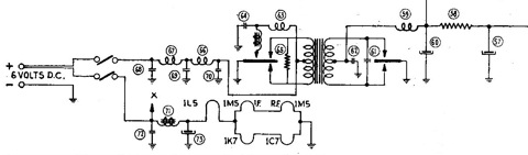
Radios that have a power source of low voltage DC require some method to generate the HT voltage. A common method, is to use a transformer with a HT secondary, but with a low voltage primary and a device to generate the AC that the transformer requires. A simple electromechanical device uses a vibrating reed to generate the AC voltage. This device is called a vibrator. The vibrator comes in several types. First there is the voltage rating, which is commonly 6, 12, 28 or 32 volts. Next there is the reed type, which can be non-synchronous, synchronous, or split reed. Most vibrators are not sealed and therefore contain air, but there are some heavy duty vibrators that are filled with an inert gas.
The vibrator is normally mounted in a sound treated tube with a valve base, so it can be changed easily. There is a coil to energise the flexible reed and a set of primary contacts to switch the DC to the transformer windings. At power on, the coil is energised, which causes the reed to swing to one side, which breaks the coil contact, and so it swings back. The cycle repeats at a frequency of about 100 cycles per second. A set of contacts switches the DC to the transformer to generate an AC voltage. The reed is usually in the negative (earth or common) lead, and the positive (hot) lead is connected to the transformer centre tapped primary winding. The contacts earth each side of the centre tapped primary, causing current to flow each way in it, similar to AC. The difference is that the current is not an AC sine wave, but a square wave.
The centre tapped secondary of the transformer is connected to a full wave rectifier valve, in the normal way, and this rectifies the AC to generate the HT voltage, which is then smoothed and filtered. This method uses a normal vibrator (called a "non-synchronous" vibrator) and has 3 or 4 pins.
The rectifier valve is not necessary if the vibrator contains a second set of contacts, which will switch the secondary voltage in synchronism with the switched DC input. This is a "synchronous" vibrator and usually has 6 pins. The HT is filtered in the normal way. If the radio design requires "back bias", then the secondary reed cannot be earthed, and must be brought out to a pin on the base. This is called a "split reed" vibrator and commonly has 7 or 8 pins.
Old vibrators that are not sealed, can be easily opened and cleaned. The contacts are usually hard tungsten, and can be cleaned with emery paper or a file. After cleaning, check with an ohm meter to ensure that no emery cloth is caught between them. The contacts can have burnt during use, or vapor from the internal padding can have deposited on them over the years. The fibre base can arc over and burn due to dirt. Remove the carbon with a rotating hand tool, and seal with silicone rubber. Re-adjust the coil contacts, so that it buzzes correctly, and starts properly (under load as well). Re-adjust the primary contacts so that they switch properly, and that they are a "break-before-make" contact.
There are several capacitors that should be inspected and changed. The HT filtering capacitors should be checked, and changed if necessary. The timing capacitor should be ALWAYS renewed. The capacitor is in the order of 0.0068uf and 1000 volt rating. This is important, as this capacitor determines the time constant (oscillation or "ringing") that occurs when the contacts open. Sometimes there is a resistor in series with the capacitor to get the correct time constant. The value is chosen with regard to the transformer inductance and vibrator frequency (and to a smaller extent the load components) so that the voltage decay coincides with the next contact closure, and (if perfect) there will be no voltage across the closing contacts, so there is no arcing or burning and consequent RF noise. This capacitor may be located on the primary or secondary winding. A cheap source of the the timing capacitors are old CRT computer monitors, as there are normally three 1000 volt capacitors in the EHT section. There are RF noise filtering capacitors in various places, the primary winding to earth, the secondary windings to earth, and possibly some input filter chokes as well. These capacitors are often mica capacitors and seldom fail.
Common vibrator faults are, open circuit coil, faulty contacts (burnt, dirty, mal-adjusted). Other faults can be, burnt or open circuit transformer, shorted or open timing capacitor, faulty HT filtering components, faulty noise filtering components.
110 VOLT RADIOS
American made radios with 110 VAC transformers are conventional and suffer the usual faults. They can be easily run on 240 VAC by using a readily available external step down transformer. Some were made for export with dual 110 volt windings, that enabled the two windings to be strapped in series for 220 volts. Sometimes a resistor may be included in the 110 volt radio or in a separate box to drop the voltage. These may burn out. Replace them with a step down transformer. A method of adapting 110 VAC radios to 240 VAC in the UK, was to use a resistive mains cord. This dropped the voltage in the same manner as a resistor does, so the cords got warm. As they broke and were shortened, they got hotter, and the radios were subjected to a higher voltage. Replace them with an external step down transformer.
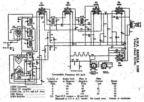
TRANSFOMERLESS SETS (AC/DC or HOT CHASSIS)
The mains transformer in a radio is expensive, so it was avoided in some designs. The rectifier valve was a half wave diode (or a full wave rectifier connected as half wave), and connected directly to the mains active lead, the other mains lead being connected to the radio chassis. There was no mains isolation, so any mains borne noise could couple into the radio. If the house wiring or the mains plug wiring became reversed, then the chassis would become live (hot) and dangerous, as the earth or aerial lead could have mains on it! They usually have a totally enclosed bakelite or plastic case, with insulated knobs, so that you could never touch a metal part. These sets could be 240 volt or 110 volt. The use of a 240 to 240v (or 240 to 110v) isolation transformer is a necessary safety item when servicing one of these. A step down transformer or a VARIAC may be an auto transformer, and if so, will not provide isolation. some TV sets from the 1990s hadnosiy and dangerous switching power supplies, and to be sold on the Australian market, they required an isolation transformer to be fitted. Look for throw out TVs on the side of the road.
Other than the danger, the power supply was simple, and had the usual faults. Be careful if using an oscilloscope or signal generator, as the earth lead can touch a mains live part and cause a huge short circuit. Another reason for the popularity of these sets in some regions, was that a transformerless set could operate on a DC mains. The rectifier would conduct normally. If the mains was reversed, it would not work at all.
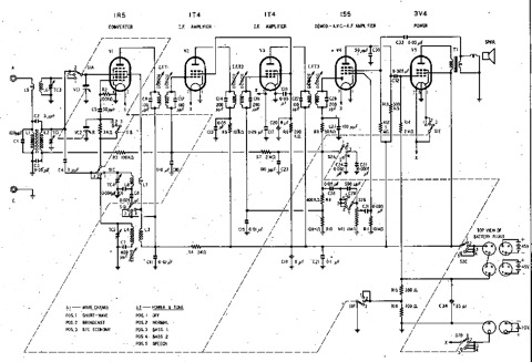
The filaments of the valves in these sets were connected in series, and normal valves were used for the RF, mixer, IF and AF preamplifier. The RF or mixer were normally at the earthy end of the series string. Since these would only add up to about 24 volts or so, there would be a special version of the audio output or rectifier valve. These have 50 or 110 volt heaters, and importantly, 110 volt cathode/heater insulation, as they were at the top of the series heater string.
A common fault is for one of these to burn out, then all the valves don't light. To determine the faulty valve, either remove them one by one and check for heater continuity, or start at the earthy end with the radio plugged in, the meter set to 240 VAC, and work up from the earthy end, until you find voltage. Don't forget the pilot lights, as they are in the chain as well, or may even be used as a fuse. If there has been a heater/cathode short circuit, the cathode capacitor and resistor may be damaged.
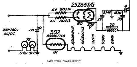
BARRETTERS
The series string of heaters can be controlled by using another method. The radio design can use valves with normal heater voltages, and a series regulator valve to control them. The common controller is called a Barretter, and is a current regulator (NOT a voltage regulator). Therefore, all the valves must have the same heater CURRENT and any that are not the same, will need a parallel resistor to compensate. The Barretter will glow and adjust the current to the correct value, regardless of mains voltage. The Barretter looks like a large light globe, with a very long filament that glows dully. It is an iron filament in a helium atmosphere, and it regulates the current, by changing its resistance with temperature. When checking the heater voltage with a voltmeter, do not worry if the voltages are not exactly right, as the current will be correct. Common faults are an open circuit Barretter filament.
There is a device called a "ballastron" which is similar in function to a barretter, but it is merely a resistor in a plugable valve like case.
Section 1
Section 2
Section 3
Section 4
Section 5
Section 6
Section 7
Section 8
Section 9