Radio Servicing Information
For use by legally qualified and licensed repairers only
Countries have laws regulating who is legally allowed to repair or work on electrical equipment that will be plugged into the mains electricity supply. This is to protect the public from the risk of electric shock. If you are not lawfully allowed to repair electrical equipment yourself, you must find an electrician, a licensed electrical mechanic or electrical contractor or electronic technician to do any work on the equipment.
Different countries use electricity supply at different voltages. The United States uses 110-120 volts AC. The United Kingdom and Australia (amongst many other countries) uses 240 volts AC. Any electric shock at Voltage 110v or above is likely to be lethal.
Many types of early consumer electronic equipment was constructed at a time when electrical safety was not as carefully considered as is required under manufacturing laws today, and many early radio sets etc have mains electricity wiring and metal mains voltage terminals fully exposed to be touched once the metal chassis is removed from the wooden case or bakelite housing.
This is why any electrical work to restore or repair an old radio must be done by a licensed qualified technician.
YOU MUST NOT ATTEMPT TO REPAIR THE RADIO YOURSELF UNLESS YOU ARE LEGALLY ALLOWED TO DO SO.
AUDIO AMPLIFIERS
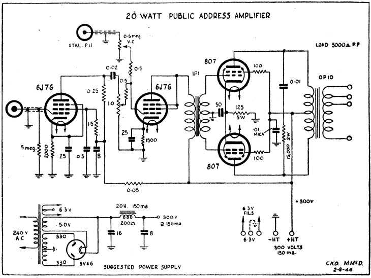
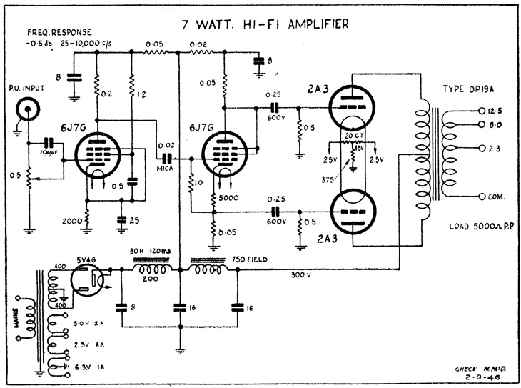
There are many versions of audio amplifiers, from simple crystal set amplifiers to public address amplifiers. They usually consist of one or more power output valves, and one or more preamplifiers. They often have negative feedback to give a flat frequency response. They may have tone controls. In a single power output valve which runs in class A, they suffer from normal faults, leaking coupling capacitors, open cathode bypass capacitors, shorted tone compensation capacitors in the anode circuit. If the power output circuit has two valves, then they may be simply connected in parallel to give more power. Or they may be connected in Push Pull. This requires a phase inverter as each valve amplifies one half of the cycle. A driver transformer is an easy way to get the phase inversion with a centre tapped secondary.

Another way to achieve phase inversion without using a transformer, is to use a driver valve with a gain of unity. The cathode circuit has a signal of zero degrees phase and the anode circuit has a signal of 180 degrees phase. Note that the phase inverter valve has a high cathode resistor and that it is not bypassed. The output valves need some sort of negative bias so that they operate in class B or class AB. The bias can be supplied in several ways, back bias, a battery, a separate negative supply, or cathode bias. In the circuit with dual 2A3 triodes, the resistor from the tap to earth is the bias resistor.

If there is negative feedback to control frequency response, it can be achieved in several ways. Having no cathode bypass capacitor is one way. Taking output from the speaker coil or plate circuit, back to the preamplifier cathode is another way. There may be a resistor/capacitor network to add some compensation. There may be a Tone control in this network.
If the amplifier has a microphone input, it may be high impedance for crystal microphones or low impedance for dynamic microphones. Dynamic inputs often have a matching transformer. If they have a record player or phono input, the preamplifier may be different.
If low output, check that the speaker is connected to the correct impedance output tapping. Also check that the cathode bypass capacitor is good. If there is any hum, check the filter capacitors first, then change each valve to check for heater cathode leakage. If the valves are directly heated, then there with be some sort of balancing for the filaments, either a tap on the transformer winding or two resistors. This may be adjustable. Sometimes the transformer is mounted so that it can be rotated to reduce magnetic coupling. This won't be a problem unless a new mains transformer has been fitted. Try reorientation. Check for corroded earths. Check valve shields on the preamplifiers.
MICROPHONES
There are many different types of microphones, but they all do the same thing, which is to convert sound pressure waves into electricity. The method used will determine the frequency response, the output level and the output impedance. Crystal microphones have a pietzo crystal, have a high output and high impedance and can directly drive an amplifier. Dynamic microphones have a moving coil in a magnetic field connected to a diaphragm, and have a low output impedance and level. They usually need an input transformer. Ribbon microphones have a metal ribbon in a magnetic field, and have a very low output impedance and need a transformer. Carbon microphones have a low resistance and need a current to work. They have a low impedance, high output, and usually need a transformer. Some microphones may have a preamplifier in them, and so will need power supplied. Higher quality microphones have a method of changing the direction in which they receive the sound. This can be simply a masking method to control how the sound reaches the microphone.
Common faults are broken wires and connectors, as microphones are often moved, especially when hand held. They are always dropped, so physical damage to the case and element are common. Check and fix any damage. Replace the element if broken. Check that any masking devices function. Check the frequency response. It is not absolutely flat, but it should suit the intended use, speech or music. An easy way is to put the microphone in a padded cardboard box, with a small speaker. Connect the speaker to an audio signal generator, and the microphone to an amplifier an oscilloscope. Change the audio signal generator, and look at the signal for distortion and level. Remember that the speaker is not perfect, so allow for it. Try different audio levels, soft and normal.
RECORD PLAYERS
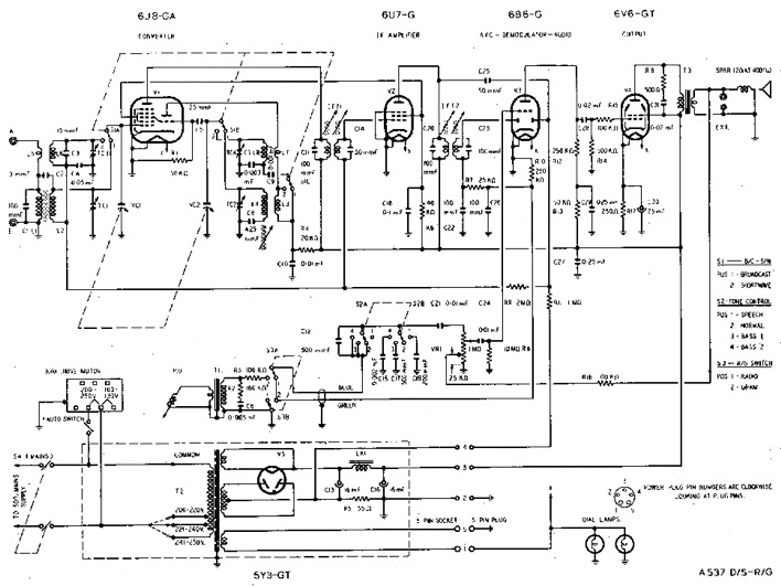
A record player may have just an audio amplifier, or have a radio as well. The radio version has an input, after the radio's audio detector, and a switch connects the input to the record player or radio. A normal crystal pickup on a record player is high output and has a fairly flat frequency response, so it can be directly connected to the input. If the pickup is magnetic, it will have a lower output, and a sloping frequency response. An RIAA (Recording Industry Association of America) amplifier is required which corrects the sloping response. Some early HiFi systems had several frequency responses that could be selected.
Normal faults are noisy switches, and hum. Clean the switch. For hum, check that the fine wires that connect to the record arm are not broken and are connected correctly. Simply touching the needle should produce a noise. Always check the needle, as it is usually dirty, and if so, clean it with water and a fine brush. Be gentle. Look at the needle with a magnifying glass to check for wear, and replace if worn. Check the counter-balance under the record arm, that the spring is working and reducing the weight on the needle.

TURNTABLES
The turntable has a round platter driven by a motor with some type of gear reduction. The early types were a single speed. Later types had some sort of gear change, to allow the playing of the older 78 RPM records, 45 RPM singles, 33 RPM albums, and 16 RPM speech records. Often it was a stepped motor shaft, with an idler wheel that moved from place to place, to change the ratios. The idler wheel runs on the inside of the platter, and is moved by a lever.
The idler wheel will lose its rubber completely, or get a flat where it has been resting against the platter or motor for many years. This will cause it run at the wrong speed, or give an audible bump in the sound. Replace the wheel. If the record runs at the wrong speed, put a stroboscope on the platter, and shine a normal mains powered light on it. The 50hz flashing of the light, should show a steady pattern on the stroboscope. If running slow, check and lubricate the bearings. Change the idler wheel. Check that the motor is made for 50 hz and not 60 hz. Some motors had a spare shaft, and you could fit the one for your mains frequency.
Section 1
Section 2
Section 3
Section 4
Section 5
Section 6
Section 7
Section 8
Section 9

